

INTRODUCTION
Motion analysis is a medical assessment technique used to diagnose pathological movements. Furthermore, a three-dimensional camera system is an accurate method to obtain the information about the kinematics. However, that kind of system has some limitations; such as the requirements of skill and experience, the high cost of the system (more than US$320,000 for a full system in Thailand), and its applicability for mostly indoor laboratories [1,2].
Nowadays, the application of close-fitting sensor technology is a relatively new technique that is used for the measurement of human movement, with obvious benefits, such as mobility and inexpensiveness. The application of an Inertial Measurement Unit (IMU) sensor for the joint angle measurement is a notable technique of this decade [2,3,4,5,6,7,8,9,10,11]. However, different types of IMU sensors have been used, as well as different methods of the angle calculation from the sensor outputs, and different standard systems were used as the reference. Most studies used IMU sensors to measure the movement that were within 6┬░ of freedom from the accelerometer and the gyroscope [2,3,6,7,8,9,10,11]. This study used a 9┬░ of freedom Razor IMU-AHRS compatible (a triple-axis accelerometer ┬▒16 g; a triple-axis gyroscope ┬▒2,000Ōäā per second; and a triple-axis magnetometer ┬▒4 gauss and ┬▒8 gauss), with the four units attached to both of the thighs and the shanks, and then a calculation of the knee angles. This angle calculation, by means of the Direction Cosine Matrix (DCM) algorithm [12], estimated the angles by the nine parameters that consisted of three parameters from an accelerometer, three parameters from a gyroscope, and three parameters from a magnetometer. The requirements for the IMU devices developed for this study were 1) they must be appropriate sizes; 2) they must be closely attached to body segments; 3) they do not obstruct the leg movement and must be used without space limitation; and 4) they have to immediately report the angular motion data.
The validity data of the devices is an important consideration, according to the standard for developmental measurement devices. Thus, the other purpose of this study was to compare the angular motion data of the IMU system in this study, with a Qualisys motion tracking system. The validation studies for the IMU measurement were evaluated by the root mean square (RMS) of different angles and the intraclass correlation coefficient (ICC) values.
MATERIALS AND METHODS
The IMU devices
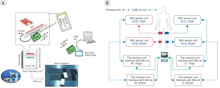
Four IMU sensors (SparkFun Electronics, Niwot, CO, USA) were used to develop these IMU devices, which consisted of two sets of IMU model number SEN-10125 and two sets of IMU model number SEN-10736. The data from the developed IMU devices links to a computer via wireless technology. For wireless technology, this study used eight sets of XBee Pro 50 mW Wire Antenna - Series 2 (ZigBee Mesh) (SparkFun Electronics) and four sets of XBee Explorer Regulated (SparkFun Electronics). Furthermore, the angular output data into the four IMU devices was transmitted to the computer by the four sets of Mini Xbee USB Dongle (Venus Supply Co. Ltd, Bangkok, Thailand) via USB ports. The power supplies of the IMU devices were four sets of Polymer Lithium Ion Battery (850 mAh output 3.7 V) (SparkFun Electronics). The Arduino code was burnt into the IMU sensors for the operating sensor, the angle calculation, and the data transmission.
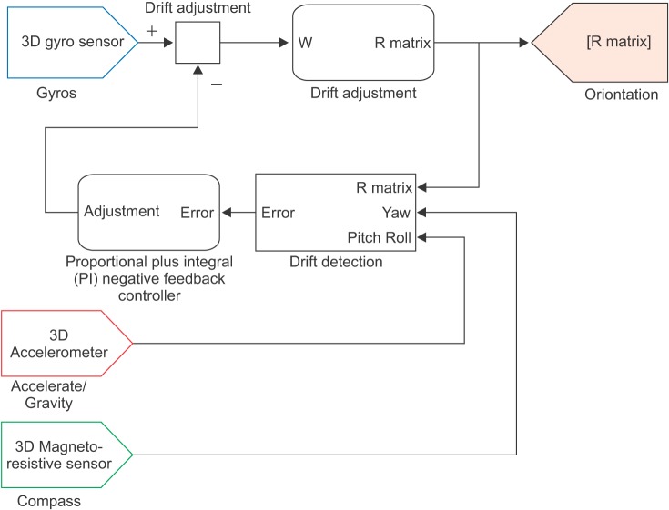
To calculate the angles on the IMU devices, the DCM algorithm used the outputs from the accelerometer, gyroscope, and magnetometer as the components for the angle calculation (Fig. 1). The acceleration outputs are used to calculate the angular motion data of the pitch and the roll. The gyroscope outputs, which report the angular velocity, are integrated to find the vector of angular motions in three planes (roll, pitch, yaw). The magnetometer outputs are used to calculate the heading of a sensor. Consequently, the outputs of all sensors are processed by an on-board ATmega328 microcontroller, and also calculate the rotation matrix (R matrix) [12]. The R matrix in terms of Euler angles is multiplied by the angular motion data in the sensor coordination frame and transforms the angular motion data in the global coordination frame. This algorithm helps to reduce an error on the joint angle measurement. Before using the IMU device, the IMU device must be placed on a flat floor during the opening sensor to calibrate and collect the basis of the global coordination frame. The process of the DCM algorithm occurs every sampling data. This IMU system was set at 50 samplings per second.
(1)
From the first and second equations, the yaw angle (╬©) is the rotate sensor around the Z-axis. The pitch angle (╬Ė) is the rotation sensor around the Y-axis. The roll angle (ŽĢ) is the rotation sensor around the X-axis. The Qg is the resultant vector of the angular motion data in the global coordination frame. The Qs is the resultant vector of the angular motion data in the sensor coordination frame. The R is the rotation matrix. The angular motion data are each of the vector component from the Qg.
Each IMU device was built in the set of an acrylic box and is attached to the body segments using a Velcro strap (Fig. 2A). Four units of the IMU devices were used to record the angular motion data of the thighs and the shanks (Fig. 2B). The knee angles were calculated from the difference of segment's angle between the thigh's angle and the shank's angle on the same side, and during the same recording time period via the Knee Angle Recorder software.
The Knee Angle Recorder software
The Knee Angle Recorder software was used to cooridinate between the IMU devices our developed for this study and a computer. It was constructed by the Microsoft Visual C# 2010 Express (free license software for a personal user). This software can set the recording time at a range of 5 to 60 seconds. Also, the user can press the 'start' command to begin the data transmission from the four IMU devices to the computer at any given time. The software works to receive the angular motion data from the four IMU devices and then immediately displays the four line graphs of the changed angles (in degrees) versus time (in seconds). The four line graphs represent the angular motion data from the thighs and the shanks in three planes (sagittal, coronal, and horizontal). The knee angular motion data is calculated from the angular motion data of a thigh and a shank from the same side and the same recording time. Finally, the angular motion data can be saved as an ASCII file.
The basic tests for the validity of reading angles from the IMU devices in this study
Previously, we tested the inclined sensor that was set in an acrylic box. The results showed that all the IMU devices developed for the study had an inclination of a sensor from the zero line of less than ┬▒1┬░ on both the sagittal and the coronal planes. Moreover, in this study we tested for the validity of reading angles on both the sagittal plane and the coronal plane, and then tested for the static condition and the dynamic condition. For these tests, IMU devices developed for this study were separated into two pairs. The first pair was sensor number 1 and 2, which was regularly used to measure the angular motions of the right leg. The second pair was sensor number 3 and 4, which was regularly used to measure the angular motions of the left leg. The results showed that the RMS of different angles and the ICC values between the reference angles and the reading angle from first and second pairs of IMU devices in the static conditions were less than 2┬░ (ICCŌēź0.99). The RMS of different angles were less than 3┬░ (ICCŌēź0.98), compared with the dynamic conditions between the IMU system and the Qualisys system [13]. However, the IMU system developed for this study could not report the validity of angular measurement in the horizontal plane.
The camera motion tracking system
The reference system was the Qualisys system (Qualisys AB Company, Gothenburg, Sweden), which is a standard method to measure the human movement. There are the six cameras (120 Hz). The size of the reflective markers is 1 cm in diameter. The joint angular motion is calculated from the positions of the reflective markers, using the relative angle method. This study took place at the Excellence Center for Gait and Motion at King Chulalongkorn Memorial Hospital and the Biomedical Engineering Laboratory, Faculty of Engineering, Chulalongkorn University, Thailand.
Subjects
Ten participants (7 men, 3 women), who walked normally, were recruited for this study. Their ages ranged from 23 to 34 years old; the mean (standard deviation) was 26.8 (3.68) years old. The body mass index ranged from 17.91 to 26.93 kg/m2. The leg length difference, between the left side and the right side, differed by less than or equal to 1 cm. This research was approved by the Institutional Review Board, Faculty of Medicine, Chulalongkorn University, Thailand.
Procedure
After the completed calibration of the Qualisys system and the IMU system, the participants were asked to wear shorts. Four units of IMU devices were attached to the anterior mid-thigh and the anterior mid-shank on both sides, by the use of Velcro straps. Reflective markers were placed on the standard positions for the recording of data from the lower limbs, as measured by the Qualisys system. The researchers recorded the markers' positions on a participant's body that was in the upright position. Also, the participants were asked to move their legs according to the specific instructions. Four movement tests consisted of the knee flexion test, the hip and knee flexion test, the forward step test, and the leg abduction test (Fig. 3A, B ,C, and D). After finishing a requested movement, a leg was moved back to the starting point. All movements were tested on both legs. Finally, the participants were asked to walk along a walkway at their normal speeds (Fig. 3E), and then the angular motion data of a gait cycle was selected for comparison.
Protocol of analysis
The angular motion data from the Qualisys system and the IMU system was exported to an ASCII file type. The ASCII files were imported to Microsoft Excel (Windows) and were plotted on line graphs of the changed angles (in degrees) versus time (in seconds). The Qualisys system set the sampling data at every 0.0083 seconds (120 Hz) and the IMU system set the sampling data at every 0.02 seconds (50 Hz). The two systems could not concurrently start to measure the joint angles. This problem was solved by an adjustment of the start by an offset to the same starting point of the movement. The RMS of different angles and the ICC values between the two systems were calculated at the same time positions of the angular motion data. There were approximately ten positions per second.
RESULTS
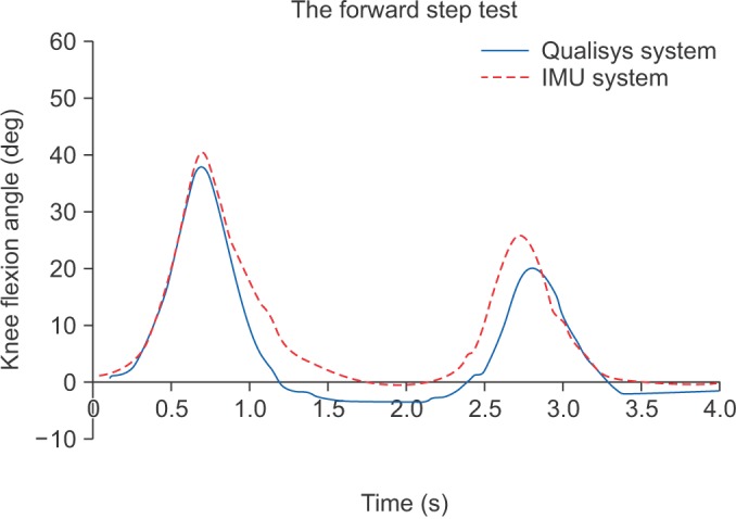
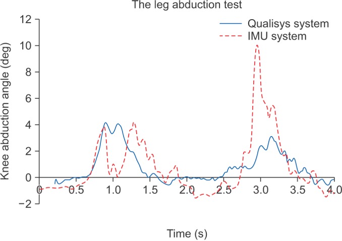
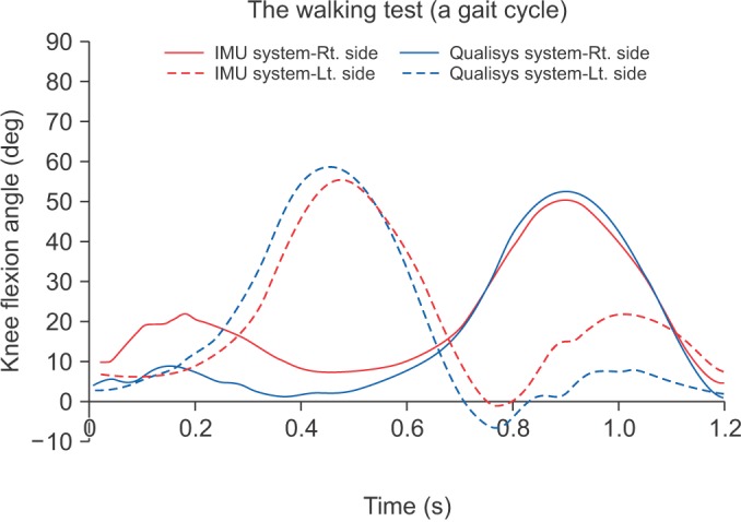
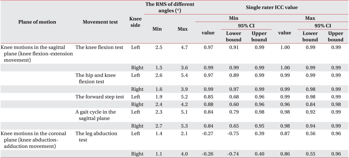
Table 1 is a summary of the RMS of different angles and the ICC values of knee angular motion data between the IMU system and the Qualisys system on both legs of the ten participants. The knee flexion-extension movement was the motion in the sagittal plane, whereas the knee abduction-adduction movement was the motion in the coronal plane. The results showed that the RMS of different angles was in the range of 6┬░ (ICCŌēź0.85) by the knee flexion test (Fig. 4), the hip and knee flexion test (Fig. 5), and the forward step test (Fig. 6). Those tests were comparison of knee flexion-extension movement. For the leg abduction test, there needs to be an evaluation of the knee abduction-adduction movement (Fig. 7). The results had a poor correlation between the two systems. The RMS of different angles on the gait cycle, which was compared with the knee flexion-extension movement, was in the range of 6┬░ (ICCŌēź0.84) during the walking test (Fig. 8).
DISCUSSION
In this study, the IMU sensors were used to develop the devices for measuring the knee angular motion data, with some obvious benefits, such as relative inexpensiveness (less than US$1,600 for the IMU system) and an ambulatory device via wireless technology (circa 120 g per unit without cable). In previous studies, the researchers applied only accelerometers or gyroscopes to estimate the joint motions [14,15,16,17], and there were also errors from the signal fluctuations in the accelerometer, as well as a distortion of the data from the offset or the integration of angular velocity [18,19]. Thus, the IMU sensor, which is combined with an accelerometer and a gyroscope, is notable for the present study [2,3,4,5,6,7,8,9,10,11]. For the angle calculation from the accelerometer outputs and the gyroscope outputs, the Quaternion-based fusion method was used, as in [3,9,10,11]; as well as a Kalman filter and strapdown integration [2,6], and the estimated orientation of segments using gravitational acceleration [7,8]. The DCM method, which was the other calculation method for the vector of motion, was used to calculate the angular motion data. The DCM method must use the nine parameters to calculate the angles. Thus, the IMU sensors with 9┬░ of freedom (a triple-axis accelerometer, a triple-axis gyroscope, and a triple-axis magnetometer) were used in this study. Hence, in accordance with this purpose, this study required devices for the knee joint angle measurement that did not obstruct the leg movement and could be used without space limitations. Hence, a wireless connection was added to the IMU devices, by use of the XBee Pro 50 mW Wire Antenna. Furthermore, there was a need to immediately display the angular motion data from the thighs and the shanks, and also the calculated knee angular motions. Thus, the Knee Angle Recorder software was developed for that need.
There were the four functional movement tests in this study. The knee flexion test was where the shank moved backward to 90┬░ of knee flexion during a stand. There was a need to evaluate the knee flexion angles when there was only movement of the shank segment. The hip and knee flexion test was the movement of thigh and shank together, until the bent hip was 90┬░ and the bent knee was 90┬░. The knee flexion angles were evaluated by the movement of the thigh segment and the shank segment, together. The forward step movement was the concurrent movement of the thigh and the shank to touch the floor in the forward direction. The knee flexion angles were evaluated during the condition that had effects on the extrinsic force (e.g., the ground reaction force). The leg abduction test was the process to move the leg to the side. In this study, there was a focus on the evaluation of knee abduction angles. Finally, the knee flexion angles in a gait cycle were evaluated during the walking test.
The results of this study showed the RMS of different angles and ICC values, which are as follows. The peak value of the RMS of different angles, in the knee flexion test, was 4.7┬░ and the ICC values were in the range of 0.99 to 1.00. The peak value of the RMS of different angles, in the hip and knee flexion test, was 5.4┬░ and ICC values were in the range of 0.97 to 0.99. The peak value of the RMS of different angles, in the forward step test, was 5.2┬░ and ICC values were in the range of 0.85 to 0.99. The peak value of the RMS of different angles, in the leg abduction test, was 4.0┬░ and ICC values were shown to have a poor correlation. The peak value of the RMS of different angles, on the knee flexion in a gait cycle, was 6┬░ and ICC values were in the range of 0.84 to 0.98. In a previous study, Favre et al. [3] tested their system on walking (30 m) and found the average root mean square errors (RMSE) was less than 2┬░ in three planes along the walking test. Dejnabadi et al. [5] tested their system during a treadmill walk at varying speeds and they found very small errors (RMS=1.3┬░, mean=0.2┬░, standard deviation=1.1┬░) and excellent correlation coefficients (0.997), compared with an ultrasound-based motion measurement system. Furthermore, other research showed good results for their systems were in the the RMS range of 0.2┬░ to 7┬░ in the flexion-extension movement; and there was also a good correlation on the walking test, compared with the reference system [6,7]. However, it was difficult to compare the results of this study with the previous reports because of different factors, such as the types of IMU sensors, the sampling rates, the standard reference system, and the methods of testing.
The different methods for the estimated angles was a factor that caused different output data from the knee angle measurement for the Qualisys system versus the IMU system used in this study. That is, the Qualisys system calculated the knee joint angle from the positions of reflective markers by a relative angle method. In contrast, the IMU system ascertained the knee joint angles from a calculation of sensor outputs (accelerometer, gyroscope, and magnetometer), and then estimated the knee joint angle by finding the difference between the angles of the segments. Thus, it is possible that the different angles between two measurement methods were caused by the various effects of force, such as the extrinsic force (e.g., ground reaction force) or the intrinsic force (e.g., muscle, joint friction).
Concerning the leg abduction test, a poor correlation was found for the angular motion data of the IMU system versus the Qualisys system. That anomaly could have been caused by many factors, such as the placement area of IMU devices, a narrow range of motions on the knee abduction-adduction movement, or the force during the movement. For example, the anterior mid-shank is not a smooth area, as the bony prominence resulted in a slight lateral tilt when the IMU device was placed on it. Despite the fact that we endeavored to fix the IMU devices on the segment by various means, such as Velcro straps. The combination of the reading angles from the IMU devices tended to be higher values from the effects of force, whereas the reading angles from the Qualisys system were lower values because of the narrow range of motion of the knee abduction-adduction movement. However, the IMU system also was a good method to measure the pattern of the knee flexion-extension movement that is an essential movement of the knee joint. Furthermore, the IMU system could immediately report the quantitative angular motion data.
One should note the following about the usage of the IMU devices in this study. That is, the IMU devices always automatically calibrate during the the opening sensor. Furthermore, before using the IMU device, it must be placed on a flat floor, and heading sensors must be pointed to the to the north during the opening sensor.
There were some limitations for the IMU devices. First, the IMU devices were restricted in their measurement of the angular motion data from the horizontal plane. Second, the IMU devices should not be placed near an electromagnetic device because the wireless signal output was disturbed by it. Third, while testing one should avoid the heading sensor pointing to the north because that caused an error of the calculated angles. Thus, during the tests, the right-hand side of the participants, pointing to the north, was avoided.
In conclusion, the IMU system used in this study could be an alternative tool for reporting on the knee angular motion patterns and the quantitative data from the knee flexion-extension movement. A comparison showed that a small error of less than 6┬░ was found for the RMS of different angles. The advantages of the IMU system are its inexpensiveness and use as an ambulatory device for continuously monitoring knee movement during its various functions.